The Switch In The Circuit In Figure 1 Has Been Closed A Long Time At T
0 It Is Opened
The Switch In The Circuit In Figure 1 Has Been Closed A Long Time At T 0 It Is Opened. At $ t=0^+ $, the rate of change of current through. Consider the circuit shown in figure $\mathrm{p} 4.40$ a voltmeter (vm) is connected across the inductance.
Solved The Switch In The Circuit Below Has Been Closed Fo from www.chegg.com
The ammeter model is placed in the branch as shown in the figure. In the circuit shown below, suppose the circuit is initially open. It is then suddenly closed.
The Hunters Who Have A Reading Zero M Pierre In Your Question.
Take c 1 = 3.00 µf, c 2 = 6.00 µf, r 1 = 4.00 kω, and r 2 = 7.00 kω. In the figure, the switch was closed for a long time before opening at t = 0. At $ t=0^+ $, the rate of change of current through.
When T < 0, The Switch Is Closed, And The Inductor Acts As A Short Circuit To Dc.
Current in 4 ω resistor at t = 0 +, The switch in figure 7.7 has been closed for a long time. In the circuit of figure p28.39, the switch s has been ope for a long time.
Calculate The Initial Energy Stored In The Capacitor.
The switch in the figure has been open for a long time. At t = 0, the switch is opened. Find the value of r so that 10% of the initial energy stored in the 10 mh inductor is dissipated in r in 10 !s.
Since The Current Through An Inductor Cannot Change Abruptly, I(0) =.
Calculate i(t) for t > 0. The circuit shown consists of two identical resistors a and b, a capacitor c, a switch s, and an ideal source of emf v. The switch in the circuit shown has been closed for a long time.
The Switch In The Circuit Of Fig.
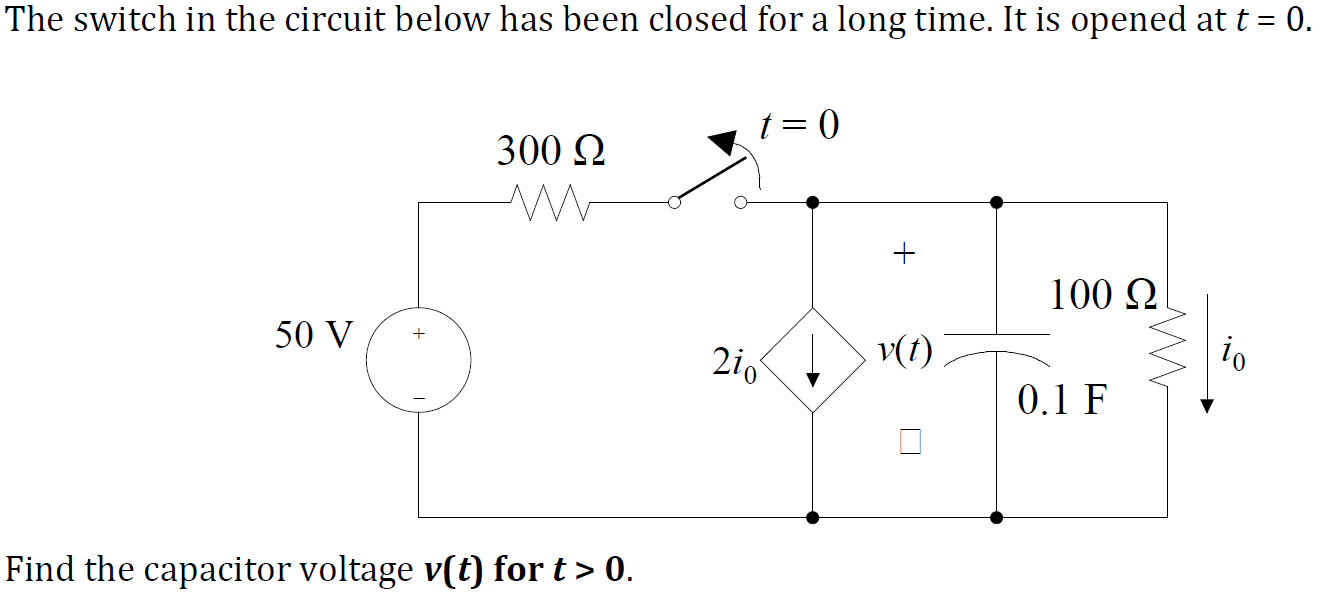
The switch has been closed for a long time. The switch in the circuit has been closed for a long time, and it is opened at time t = 0. We want to find the capacitor voltage v(t) for t ≥ 0.